A comprehensive engineering guide comparing industrial rotary screw vs. reciprocating piston air compressors, FRL units, and pneumatic distribution lines for Pakistan manufacturing facilities.
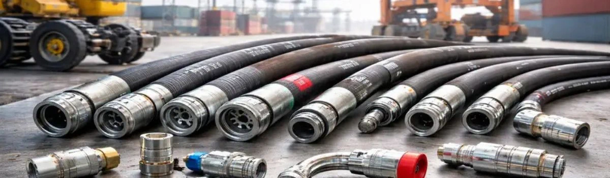
Often categorized as the fourth utility alongside electricity, water, and natural gas, compressed air powers the automated backbone of Pakistan’s manufacturing sector. From textile spinning and weaving mills in Faisalabad and pharmaceutical packaging cleanrooms in Karachi (Korangi, SITE, Port Qasim) to automotive assembly in Lahore and food processing facilities across Punjab, reliable pneumatic pressure is indispensable.
However, improper compressor sizing, misconfigured airline distribution, and untreated moisture contamination frequently lead to premature pneumatic cylinder failure, sticking solenoid valves, rusted air tools, and costly production stoppages.
Understanding the operational differences between reciprocating piston compressors and rotary screw compressors, alongside proper FRL (Filter, Regulator, Lubricator) deployment and hose line selection, is vital to maximizing plant uptime and minimizing utility bills.
Rotary Screw vs. Reciprocating Piston Compressors
Selecting the right compression technology depends on operating duty cycles, continuous air demand (CFM), and air quality tolerances:
1. Reciprocating Piston Air Compressors (1 HP to 25 HP)
- Mechanical Principle: Piston compressors use a crankshaft-driven connecting rod to move one or more pistons inside cast-iron cylinders, drawing air in through intake valves and compressing it into a receiver tank.
- Duty Cycle Limitation: Standard industrial piston units operate on a 50% to 60% duty cycle. They require intermittent cooling intervals to prevent thermal breakdown of cylinder lubricants and head gasket failure. Continuous operation leads to overheating and excessive carbon buildup on valves.
- Suitability: Piston units are ideal for automotive repair garages, tire shops, batch spray booths, light fabrication shops, and workshops where air demand is periodic rather than uninterrupted.
2. Rotary Screw Air Compressors (10 HP to 250+ HP)
- Mechanical Principle: Rotary screw compressors utilize twin intermeshing male and female helical rotors (air ends) housed within an oil-flooded chamber. Air is drawn into the rotor flutes and continuously compressed as the pocket volume reduces along the axial path.
- 100% Continuous Duty Cycle: Engineered with no reciprocating masses or internal valve flutter, rotary screw units are designed to run 24 hours a day, 7 days a week under continuous full load without thermal degradation.
- Acoustic & Flow Benefits: Operating at significantly lower sound levels (62 to 72 dB vs. 85+ dB for pistons), screw compressors deliver smooth, pulsation-free airflow directly into distribution headers, prolonging regulator and valve life downstream.
Technical Comparison Matrix: Screw vs. Piston
Slashing Energy Overhead: VFD (Variable Frequency Drive) Inverter Screws
In industrial regions governed by steep time-of-use tariffs from K-Electric, LESCO, and FESCO, compressed air generation typically accounts for 20% to 30% of a plant’s total electrical consumption.
Fixed-speed screw compressors regulate airflow using traditional load/unload modulation. When air demand drops, the motor continues idling at 40% to 70% of full electrical load without producing useful compressed air.
VFD Inverter Rotary Screws automatically modulate motor speed in direct proportion to real-time CFM consumption:
- Eliminates energy-wasting idle cycles, slashing electricity consumption by 15% to 35%.
- Soft-start inverter drives prevent heavy inrush current spikes (which trigger peak power penalty charges on industrial tariffs).
- Maintains ultra-tight pressure stability (±0.1 bar), preventing pneumatic speed fluctuations in delicate automated pick-and-place robots.
Combating Karachi's Coastal Moisture & Humidity
Karachi’s coastal atmosphere routinely experiences relative humidity exceeding 75% to 85% during the summer and monsoon seasons.
A 50 HP compressor operating in 80% humidity can introduce up to 80 to 120 litres of atmospheric water into the plant distribution piping every 24 hours. When warm compressed air cools inside airline headers, moisture condenses into liquid water:
- Rust & Pipe Scale: Causes internal flaking in mild steel headers that clogs valve spools and orifice plates.
- Lubrication Washout: Flushes out factory grease from pneumatic cylinders and high-speed air motor bearings, resulting in seized pistons.
- Pneumatic Solenoid Corrosion: Causes electrical short-circuits and mechanical sticking in pneumatic manifold banks.
The 3-Tier Moisture Separation Protocol:
1. Mechanical Cyclone Separator: Positioned immediately after the compressor aftercooler to spin out up to 90% of bulk liquid water droplets.
2. Refrigerated Air Dryer: Chills compressed air down to a +3°C pressure dew point (PDP), condensing water vapor before it enters plant piping.
3. Automatic Zero-Loss Condensate Drains: Electronic level-sensing drains that discharge collected liquid without venting expensive compressed air.
Point-of-Use FRL Air Preparation: The Life Support System
Even with central refrigerated drying, point-of-use Filter-Regulator-Lubricator (FRL) modular assemblies are mandatory at every secondary machinery drop:
- Filter (F): Incorporates 5-micron pre-filtration followed by 0.01-micron micro-coalescing elements that capture sub-micron oil aerosols, atmospheric dust, and residual condensation.
- Regulator (R): Downregulates variable mainline header pressure (typically 8 to 10 bar) to the precise operating specification of downstream tools or actuators (typically 5.5 to 6.3 bar / 80 to 90 PSI). Precise regulation prevents cylinder seal blowout and excess air consumption.
- Lubricator (L): Atomizes specialized pneumatic oil (ISO VG 32 non-detergent hydraulic/pneumatic oil) into a micro-fog aerosol to continuously lubricate high-speed pneumatic impact wrenches, air motors, and heavy-duty cylinders.
Industrial Pneumatic Lines & Reinforced Hose Assemblies
Delivering compressed air and hydraulic power from main utility headers to machinery requires rugged, pressure-certified transfer lines:
- Reinforced Polyurethane & Rubber Hoses: Multi-spiral textile and wire-braided hoses withstand shop-floor abrasion, oil exposure, and repetitive flexing around robotic arms.
- Crimped Ferrules & BSP/NPT Couplings: Precision hydraulic and pneumatic hose assemblies fitted with crimped steel ferrules prevent catastrophic hose whipping accidents under pressure surges. Explore our on-site hose assembly capabilities under Custom Fabrication Services.
- One-Touch Safety Couplers: Push-to-connect fittings and vented safety disconnect couplings that safely depressurize before release, complying with international occupational safety regulations.
Browse our inventory of modular air preparation systems, pneumatic cylinders, air hoses, and quick-release hardware under Pneumatic Solutions at Alsons Hardware, or consult our engineering team for full plant line design.
Frequently Asked Questions
What is the optimal working air pressure for industrial pneumatic tools and automation cylinders?
Most industrial air tools (pneumatic impact wrenches, die grinders, drills) and automated pneumatic cylinders are engineered to deliver their rated torque and velocity at **6.2 to 6.3 bar (90 PSI)** dynamic pressure measured at the tool inlet. Operating above 7 bar causes premature seal wear and increases air leakage costs, while operating below 5.5 bar drastically degrades tool power.
What is the difference between CFM and PSI in compressor selection?
**PSI (Pounds per Square Inch)** measures the pressure or force delivered by the air stream, whereas **CFM (Cubic Feet per Minute)** measures the volumetric flow rate of air. While PSI determines whether a tool can operate, CFM determines how many tools or cylinders can operate simultaneously without pressure drop.
Can I use standard steel or PVC pipe for compressed air distribution lines in Pakistan?
Never use standard PVC or CPVC plastic pipes for compressed air systems. Under pressure surges, PVC becomes brittle and can explode into hazardous shrapnel. Best practice is to use **seamless Schedule 40 carbon steel** or modern modular aluminum piping systems, which resist corrosion and eliminate flow friction.
How often should FRL filter elements and compressor oil be changed?
In high-dust Pakistani industrial areas, FRL filter bowls should be inspected daily (or equipped with auto-drains), and 5-micron filter elements should be replaced every 3 to 6 months. For rotary screw compressors, full synthetic screw oil should be changed every 4,000 to 8,000 operational hours, alongside oil filter and air-oil separator replacements.